
Power and monitoring for railway signalling
We design integrated power supplies for signalling and telecom to RDSO specifications, and a browser-based system that shows every track circuit, signal and level-crossing gate in an automatic section as it changes.
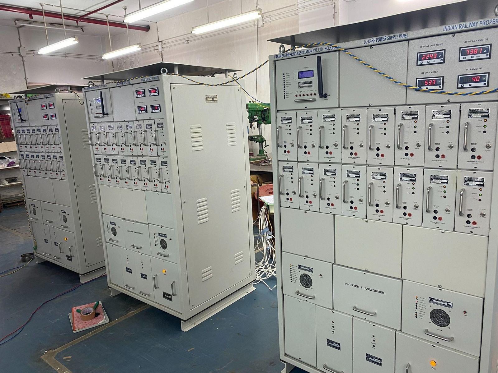
- RDSO/SPN/165/2023Integrated power supply, Version 4.0
- RDSO/SPN/215/2018LC gate IPS, Version 2.0, declared technically OK
- Two zonal railwaysTrain monitoring in service since 2013
- 901 relay inputs69 km of track on 16 PLCs
Integrated power supply to RDSO/SPN/165/2023
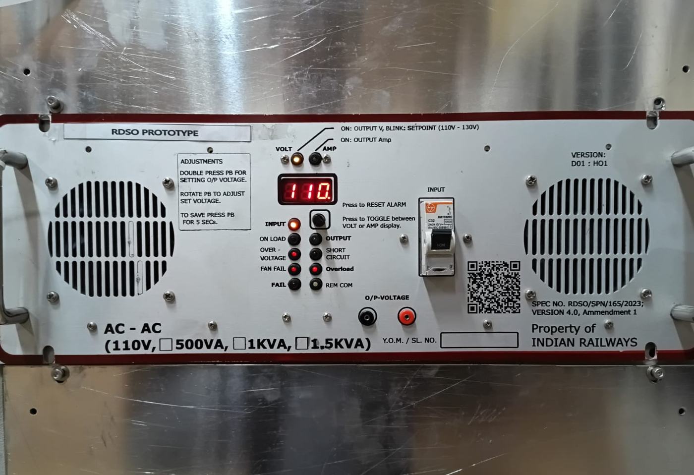
One SMPS-based system that delivers stable, uninterrupted AC and DC to every signalling circuit (point machines, signal lamps, track circuits, axle counters and block instruments) through every mains variation and outage.
Older yards fed each circuit from its own supply and battery, which was costly and left signals blank during outages. An IPS conditions the mains once and derives every AC and DC voltage from one system on one battery bank.
Algonics designs the modules, firmware and DSA. OEM manufacturers license the production-ready design and take it to approval and volume manufacture under their own brand.
What the system consists of
- FRBC charger panel
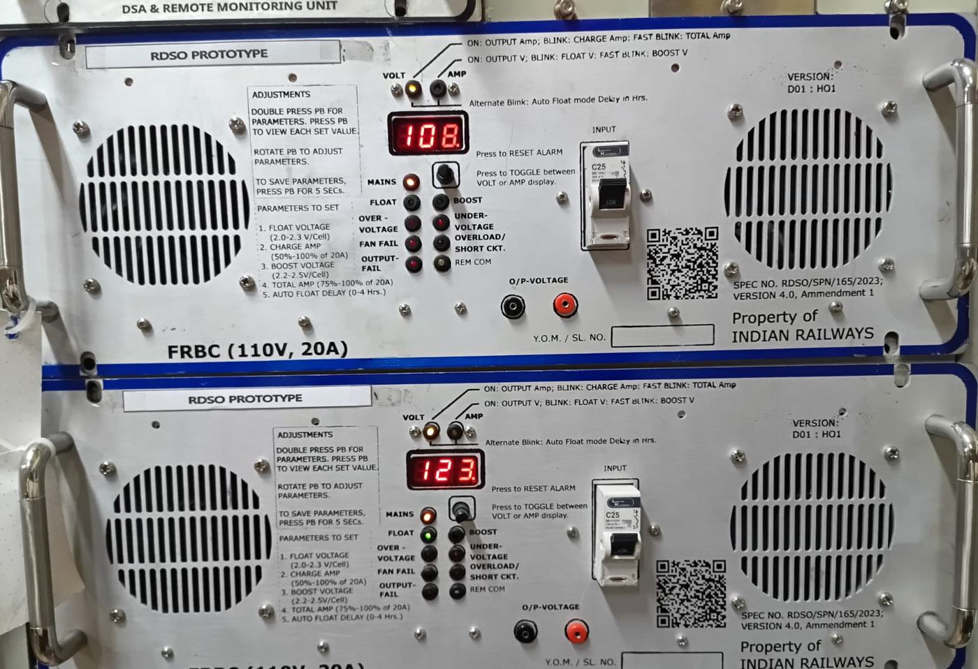
- Switch-mode float-cum-boost chargers, 110 V, 20 A per module, in N+1 load sharing with automatic float/boost changeover and programmable battery-path limits.
- AC distribution
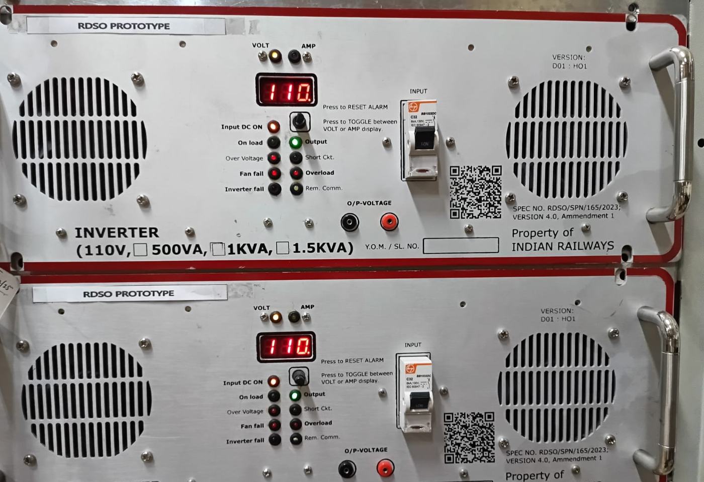
- DSP-controlled inverters, 110 V DC in and 230 V AC out up to 1.5 kVA, and voltage-regulated AC-AC converters with adjustable setpoint and automatic changeover.
- DC distribution
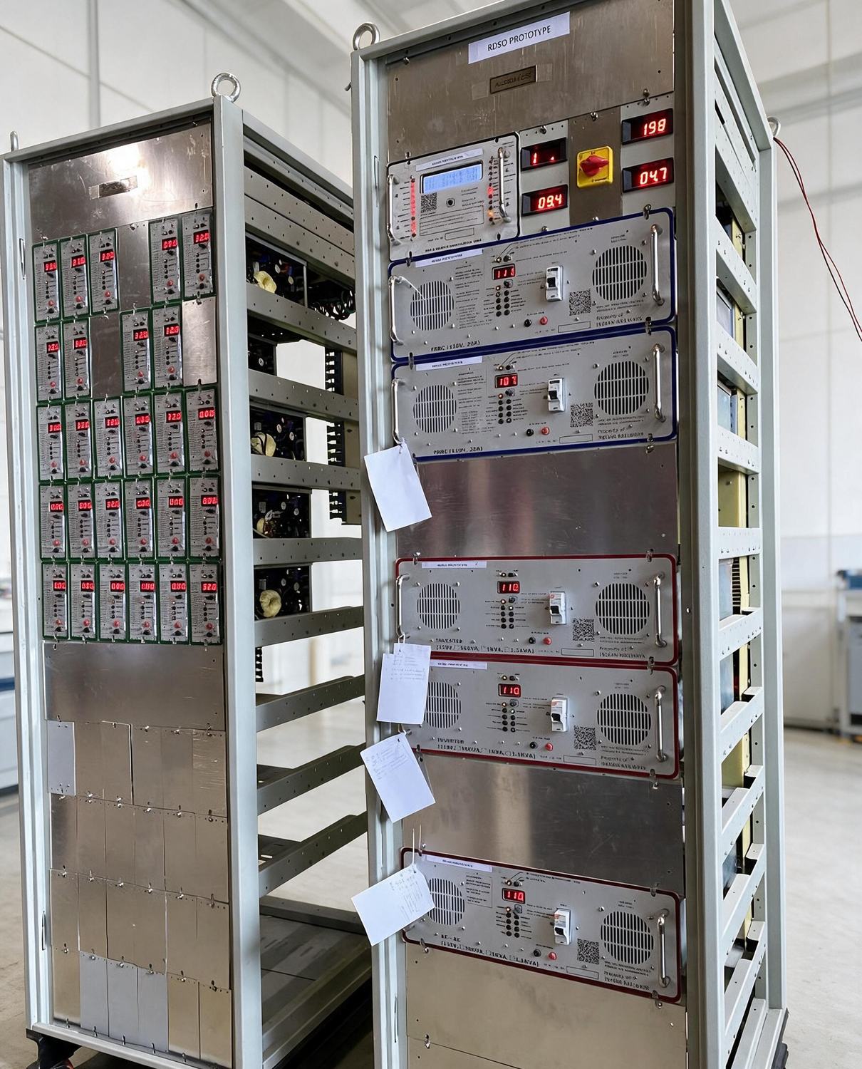
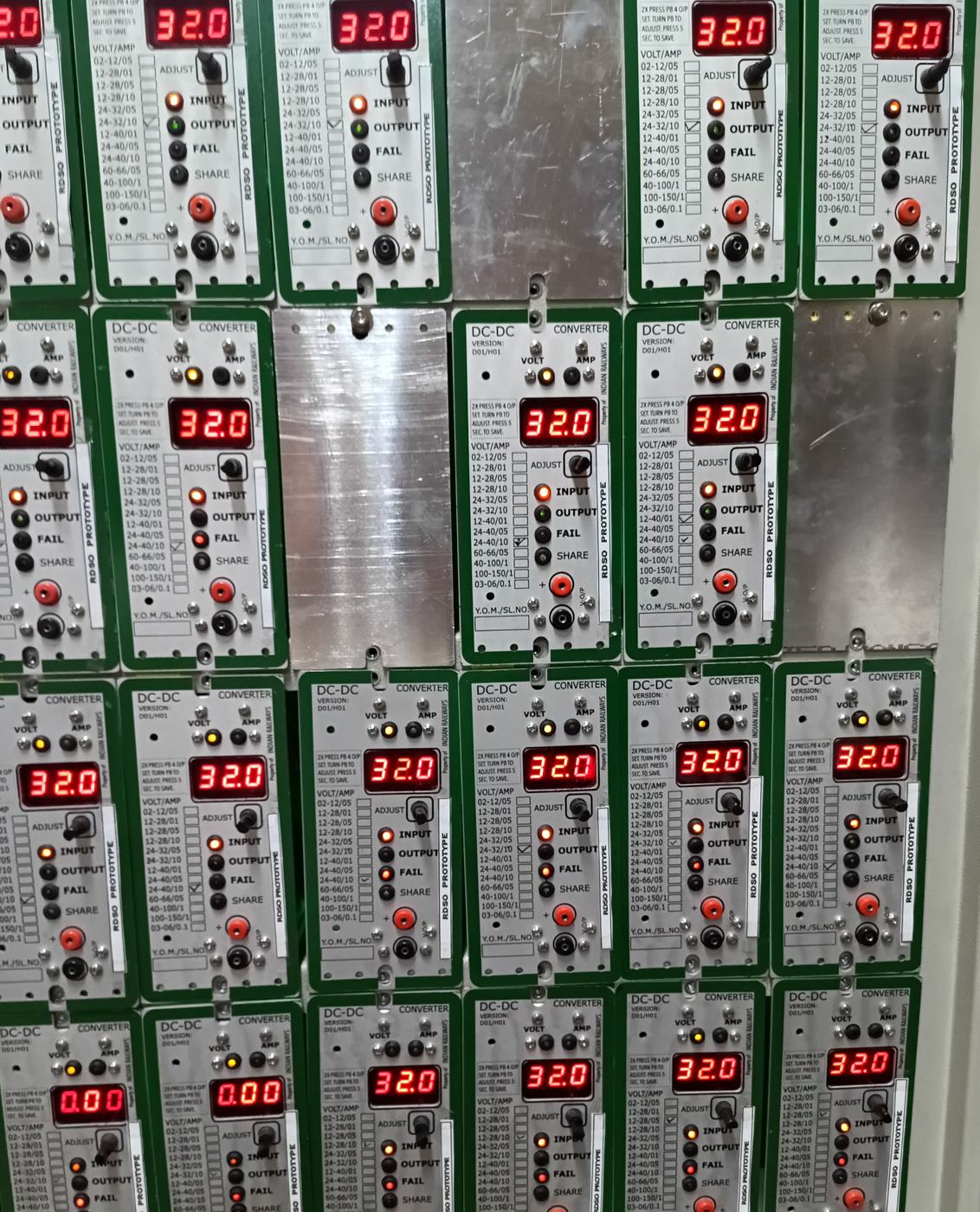
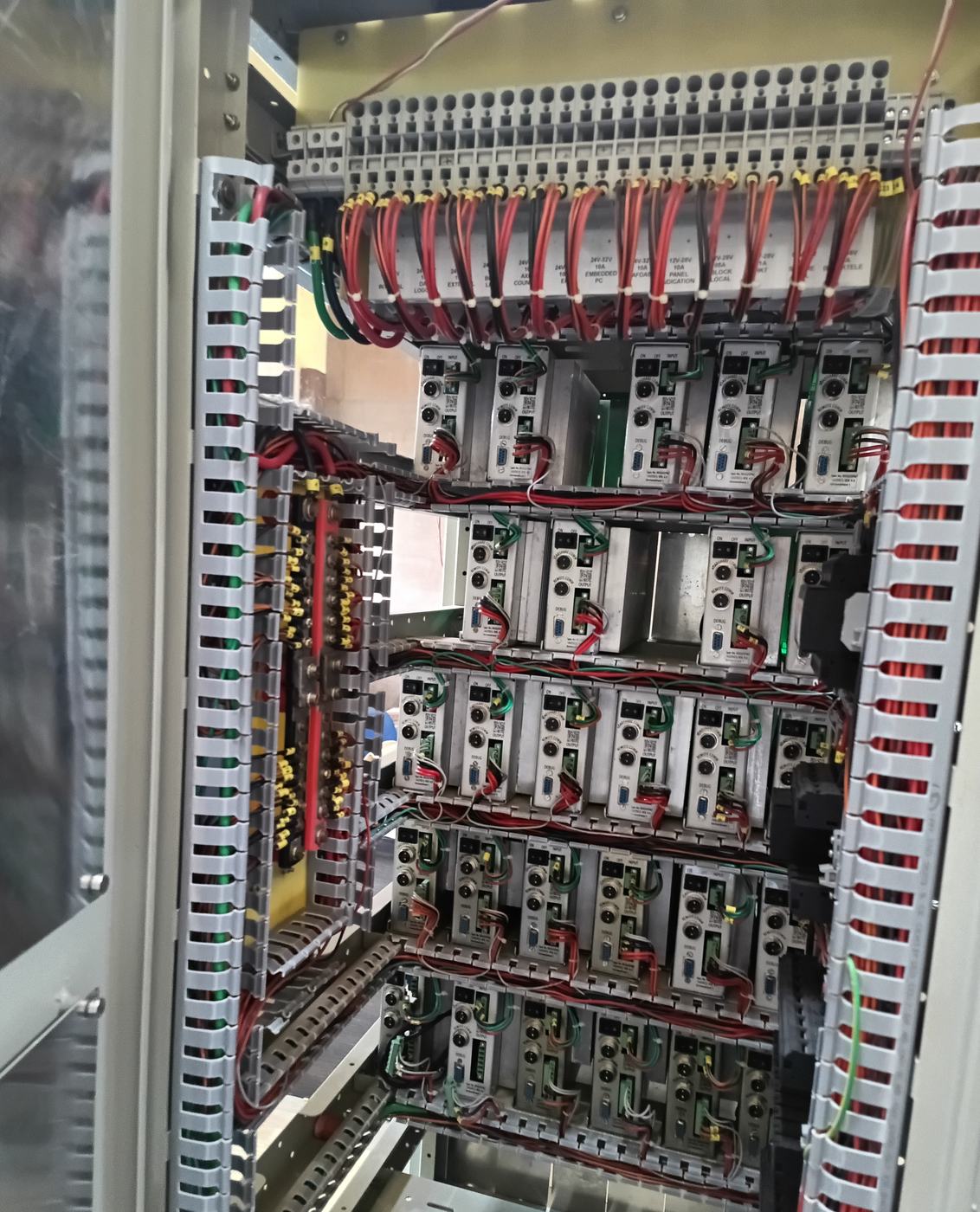
- A bank of hot-swappable DC-DC converter modules generating every signalling voltage, each with its own metering, fault indication and current sharing.
- DSA and remote monitoring
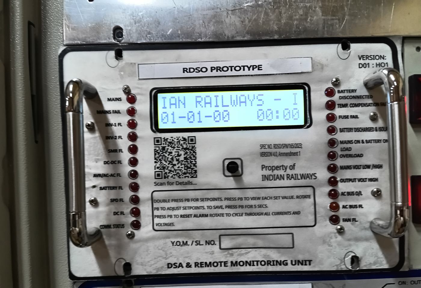
- The microcontroller-based supervisory and alarm unit: the operator interface and remote communication for the whole system.
- Battery bank and protection
- A common 110 V battery with under-voltage isolation, reverse-polarity protection, depth-of-discharge indication and lightning surge protection.
- Status panel for the ASM
- Battery depth of discharge, mains status and ‘Call S&T’ alerts in the Station Master’s room, without a visit to the equipment room.
A decade of RDSO-verified development
- 2014
Engagement with Urban Engineering
Algonics engaged as design consultant for railway power system development, starting a multi-year programme of RDSO-specification power supplies.
- 2016
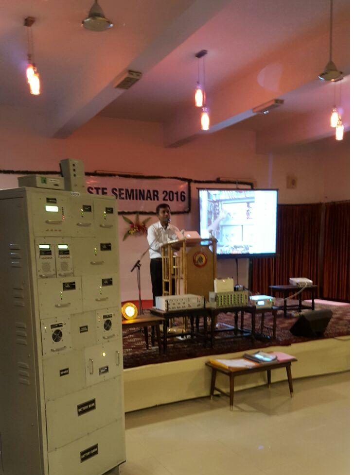
Live demonstration to S&T engineers
The full IPS rack presented and demonstrated at the STE Seminar 2016 before Indian Railways signal and telecom engineers.
- 2017
First completion certificate
Development certified complete after testing against the reference RDSO specification in the presence of RDSO officials, with satisfactory results.
- 2018–19
LC gate IPS to RDSO/SPN/215/2018 Ver 2.0
Level-crossing IPS with solar PV and MPPT. Certified in March 2019 after repeated tests before RDSO officials at our works: within specified limits and declared technically OK by RDSO, pending only environmental, dust and vibration tests at an approved laboratory.
- 2023–now
Station IPS to RDSO/SPN/165/2023 Ver 4.0
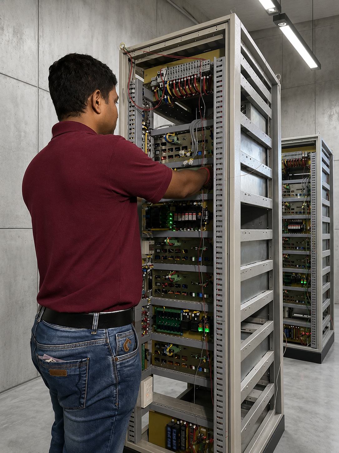
Station-class prototype racks to the latest specification: FRBC chargers, inverters, AC-AC converter, DC-DC bank and DSA with remote monitoring, engineered for OEM manufacture.
How power moves through the rack
- InputsGrid or DG set, 150–275 V AC, with Class B and C surge protection; solar PV on LC gate panels
- ChargersFRBC float-cum-boost chargers in N+1; MPPT for solar
- Battery bankOne 110 V signalling battery, temperature-compensated charging
- ConvertersInverters, AC-AC converters and the DC-DC bank
- S&T loadsPoint machines, signal lamps, track circuits, axle counters, block instruments
DSA and remote monitoring unit watches every stage and raises a named alarm for the failed module.
Built for the relay room
- Wide AC input tolerance with automatic out-of-range cut-off and restore
- High-frequency switch-mode conversion, high power factor and low THD
- N+1 parallel redundancy with active load sharing across modules
- Hot-swappable modules, replaced in under 20 minutes without shutdown
- Overload, short-circuit, over- and under-voltage, reverse-polarity, and Class B and C surge protection
- Automatic float-cum-boost battery management with temperature compensation
- Digital voltage and current metering on every module in the rack
- Solar PV with MPPT for LC gate variants at remote crossings
What the DSA reports
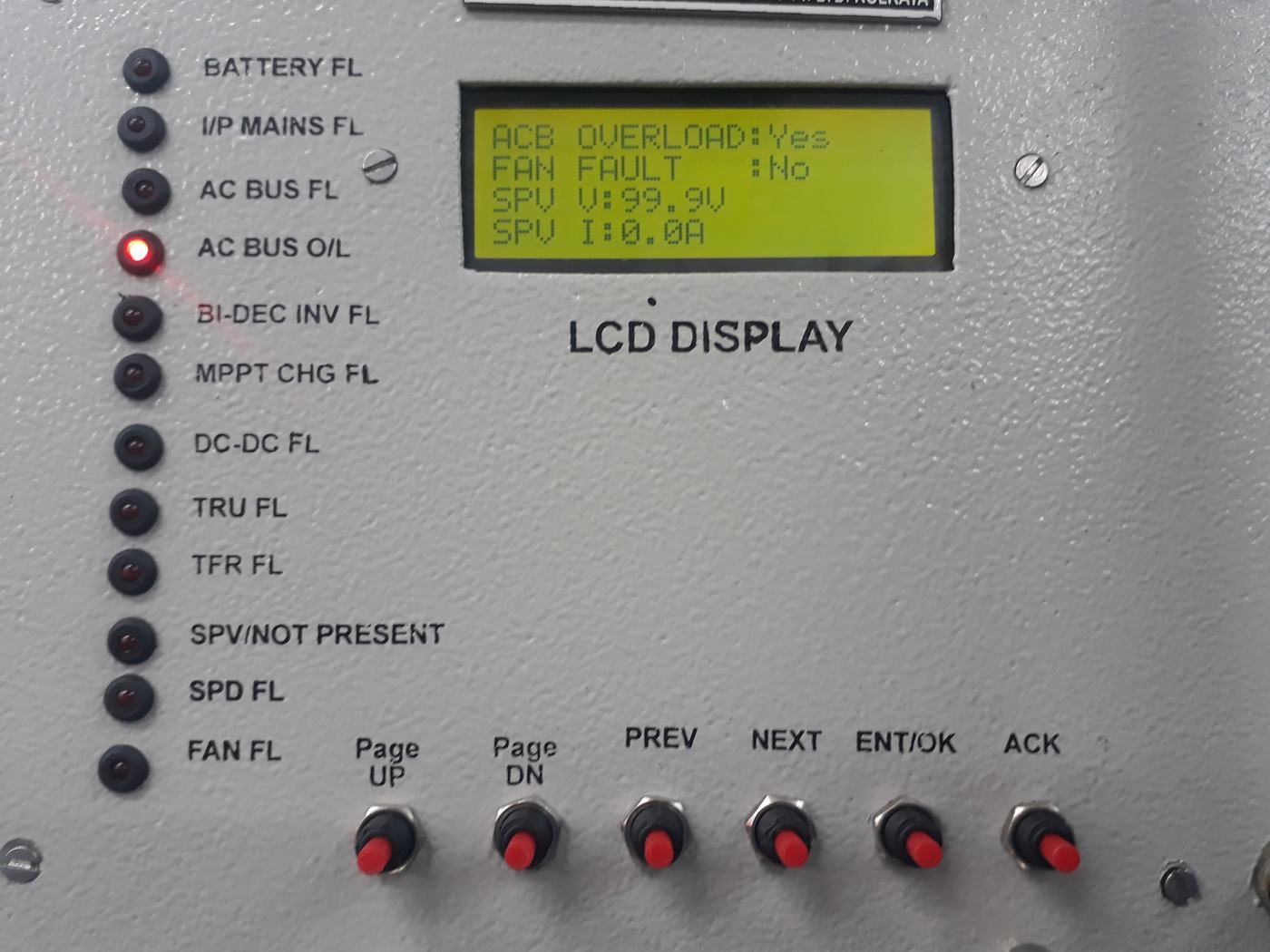
A backlit LCD cycles live voltages and currents. Setpoints are set from push-buttons, alarms are acknowledged on the panel, and a QR code links to the unit’s documentation. Every fault below is annunciated and logged individually.
- Mains fail; mains volt low or high
- Inverter 1 and 2 fail
- SMR / FRBC fail
- DC-DC converter fail
- AVR / AC-AC converter fail
- Transformer-rectifier fail
- Surge protector fail
- Fan fail; fuse fail
- Communication status
- Battery disconnected or failed
- Battery discharged and isolated
- Mains on with battery on load
- Temperature compensation fail
- AC bus fail or overload
- Output voltage high; overload
- Solar voltage and current (LC gate)
- Depth of discharge to the ASM
Technical particulars
Representative module specifications, from the RDSO specification family our prototypes were designed and tested to. Configuration-specific datasheets on request.
System
- Input voltage
- 230 V AC nominal (150–275 V)
- Frequency
- 50 Hz (48–52 Hz)
- Supply source
- Grid, DG set, solar PV (LC gate)
- Redundancy
- N+1 parallel load sharing
- Module replacement
- Hot-swap, under 20 minutes
- Ambient rating
- System 55 °C; modules 70 °C
FRBC module
- Rating
- 110 V, 20 A per module
- Charging
- Automatic float and boost; programmable voltages, auto-float delay
- Regulation
- ±1% (25–100% load)
- Efficiency
- >90% at rated load
- Ripple, no battery
- <300 mV p-p
- Battery path limit
- Programmable, 5–15% of Ah
Inverter module
- Input
- 110 V DC (98–138 V)
- Output
- 230 V AC, 50 Hz ±1%
- Capacity
- 500 VA, 1 kVA, 1.5 kVA
- Regulation
- <±2% (25–100% load)
- Waveform distortion
- <8%
- Protections
- Overload, short circuit (auto-reset), DC over- and under-voltage, fan fail
DC-DC converter module
- Input
- 98–138 V DC
- Output
- Per the railway block diagram
- Regulation
- ±1% of set value (10–100% load)
- Ripple
- <50 mV p-p
- Current sharing
- Within 10% between modules
- Protections
- Overload at 105%, tracking over-voltage
DSA and monitoring
- Display
- Backlit LCD, live voltages and currents
- Setpoints
- Push-button entry, saved on hold
- Alarms
- Individually annunciated, logged and acknowledged
- Remote
- Remote monitoring unit; status panel for the ASM
- Documentation
- QR link on the faceplate
AC-AC converter
- Output
- 110 V AC, regulated
- Capacity
- 500 VA, 1 kVA, 1.5 kVA
- Setpoint
- Adjustable, 110–130 V
- Changeover
- Automatic
- Protections
- Overload, short circuit
- Interface
- Remote communication
Configurable from wayside station to level crossing
| Installation class | Typical application |
|---|---|
| Up to 4-line wayside station | Small PI stations, RE and non-RE areas |
| 4–6 line wayside station | Mid-size PI stations |
| 6–10 line medium station | PI and EI stations, signalling load up to 15 kVA |
| Interlocked LC gate | Level crossings with solar PV and MPPT to RDSO/SPN/215/2018 |
| IBS location | Intermediate block signalling installations |
What an OEM receives
- Design package
- Schematics, PCB Gerbers, BOM and mechanical constraints: a complete manufacturing-ready set.
- Firmware and source
- DSP and microcontroller firmware for every module and the DSA, on Microchip toolchains, with documented source.
- Prototypes and FAT support
- Working racks demonstrated at our works, with support through factory acceptance testing and RDSO verification.
Power for level-crossing gates to RDSO/SPN/215/2018
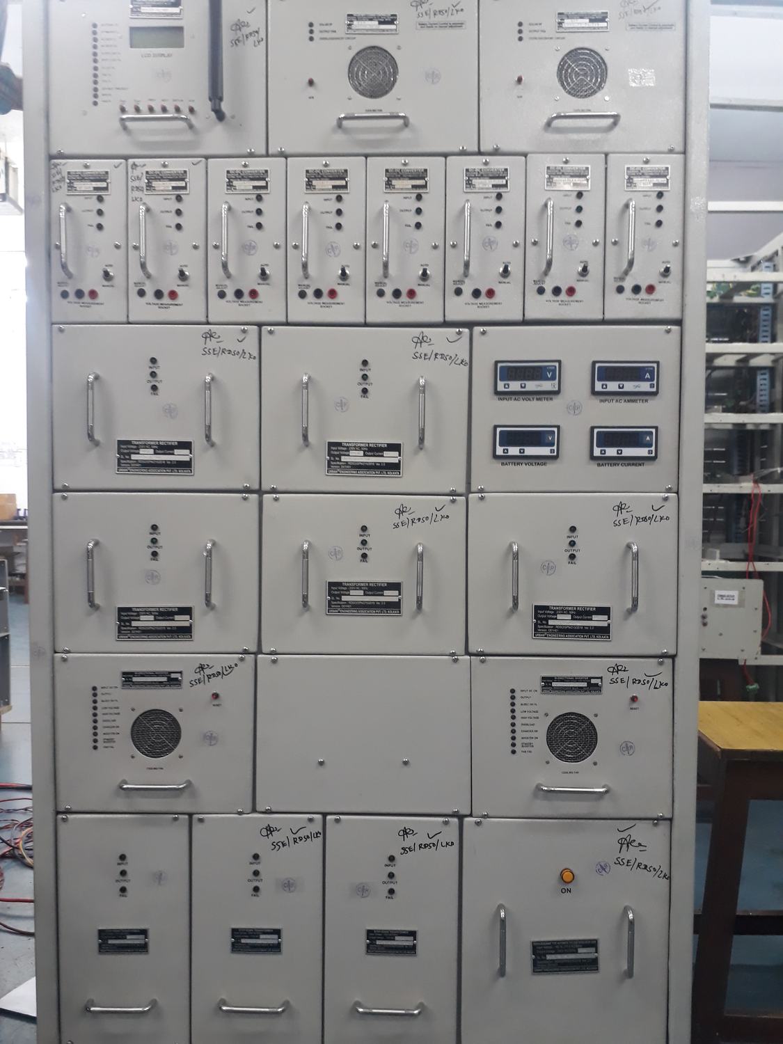
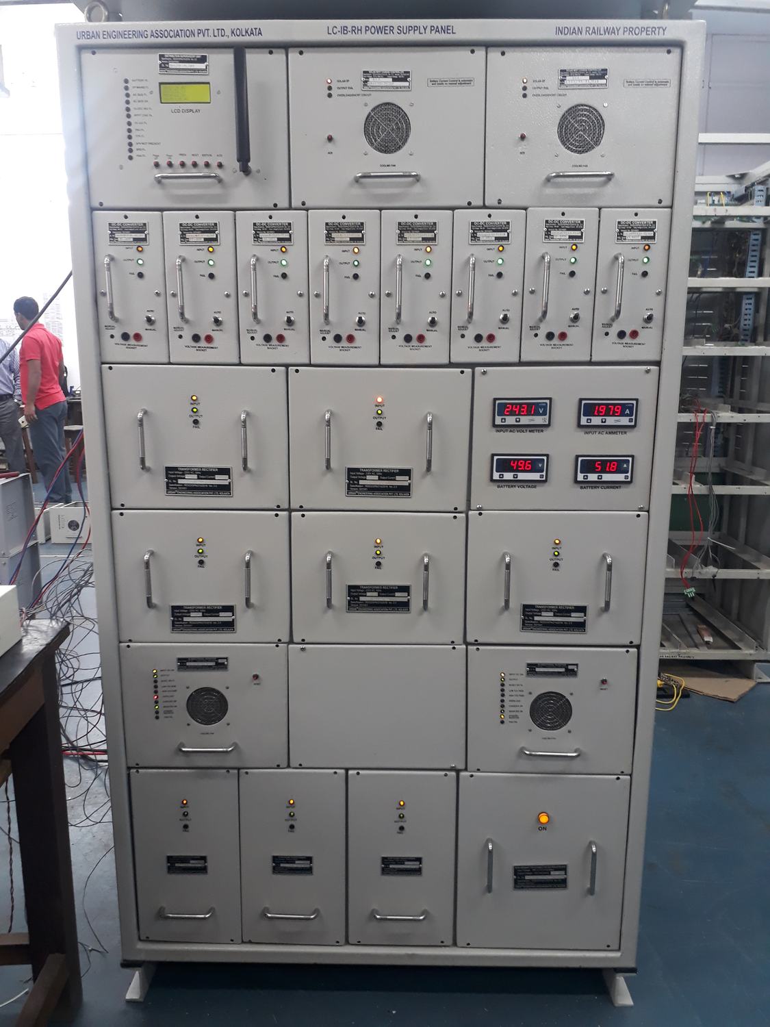
LC-IB-RH power supply panels for Urban Engineering, to Version 2.0 of the specification. Solar PV feeds an MPPT charger alongside the mains, a bidirectional inverter powers the gate equipment, and the DSA’s LCD names the fault instead of showing a single alarm lamp.
Tested repeatedly before RDSO officials at our works, the panel was found within specified limits and declared technically OK by RDSO in March 2019, pending only environmental, dust and vibration tests at an approved laboratory.
- Fault annunciation for battery, mains input, AC bus and overload, inverter, MPPT charger, DC-DC, transformer-rectifier, solar input, surge protector and fan
- Solar voltage and current on the LCD, with page-through menus on the panel front
- Completion certificates in 2017 and 2019
IPeTMS
IP-enabled train monitoring
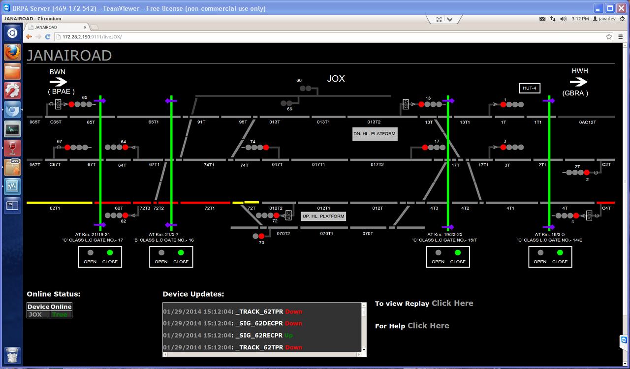
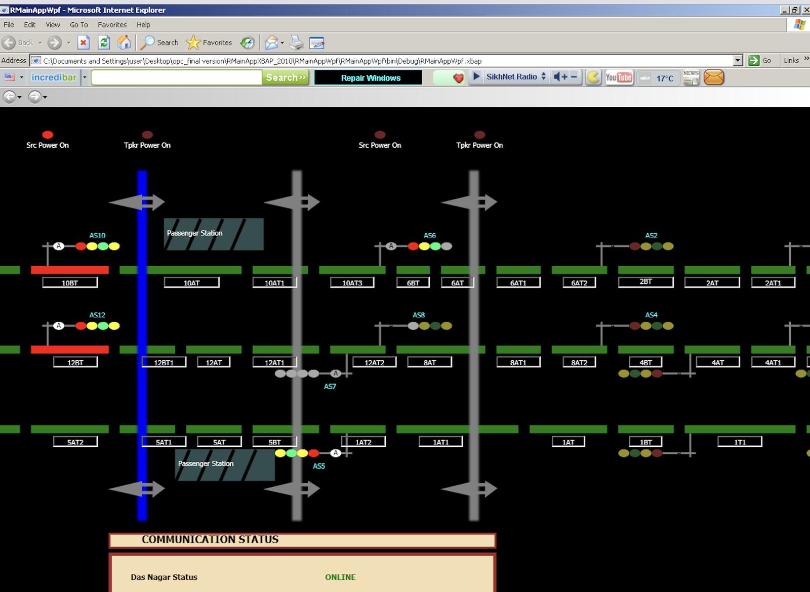
A web application that reads the relay contacts in every hut of an automatic signalling section and draws the whole section, live, in any browser on Railnet: track circuits, signal states, point machine positions and LC gates. Built by the Urban–Algonics joint venture, tested against RDSO specifications and in revenue service on Eastern and South Eastern Railway since 2013.
Two sections, documented
South Eastern Railway: Santragachi–Tikiapara
Pilot in the Kharagpur division under Indian Railways Vision 2020 for unified IP communication, in continuous operation from January 2013. Documented by SER’s Chief Signal Engineer in IRISET’s Gyandeep.
- Auto section
- 3.5 km
- Track covered
- 14 km
- Stations
- Santragachi (outer), Ramrajatala, Das Nagar, Tikiapara (outer)
- Relay huts with PLCs
- 8
- Relay inputs wired
- 282
- Server
- 1, at Santragachi, on Railnet
Eastern Railway: Dankuni–Kamarkundu
Commissioned 21 May 2013 and running from 31 May 2013 under the section’s full traffic of 215 trains a day: 70 local, 105 mail and 40 goods. The performance report records it as reliable and stable, with trouble-free working.
- Auto section
- 15 km
- Track covered
- 55.12 km
- Stations
- Dankuni (outer), Gobra, Janai Road, Begampur Halt, Baruipara, Mirzapur-Bankipur, Balarambati, Kamarkundu (outer)
- PLC locations
- 8
- Relay inputs wired
- 619
- Server
- Baruipara relay room, linked to Railnet over E1
What it changed on the ground
The whole section on one screen
Station masters see every track circuit, signal aspect and LC gate between stations. They can see exactly when a train has cleared a gate, which the published report credits with better punctuality.
Faults found from the relay room
The PLC’s ladder logic shows which relay in a circuit failed to pick up, so maintainers can tell a field-gear failure from an internal relay failure.
Every change on record
Each relay transition is stored with a timestamp. Any period can be replayed to diagnose a fault.
No client software
Any computer on Railnet with a standard browser can open it, and any railway engineer can reach it from any relay hut on the LAN. There is nothing to install and no per-seat licence.
Less copper to the station
Repeating auto-section indications to a station normally needs a conductor pair per indication. Here they travel as data on a single spare pair.
Section-wide, not one logger at a time
Conventional data loggers show one RTU or DTL at a time. This system shows every hut in the section together.
Three independent layers
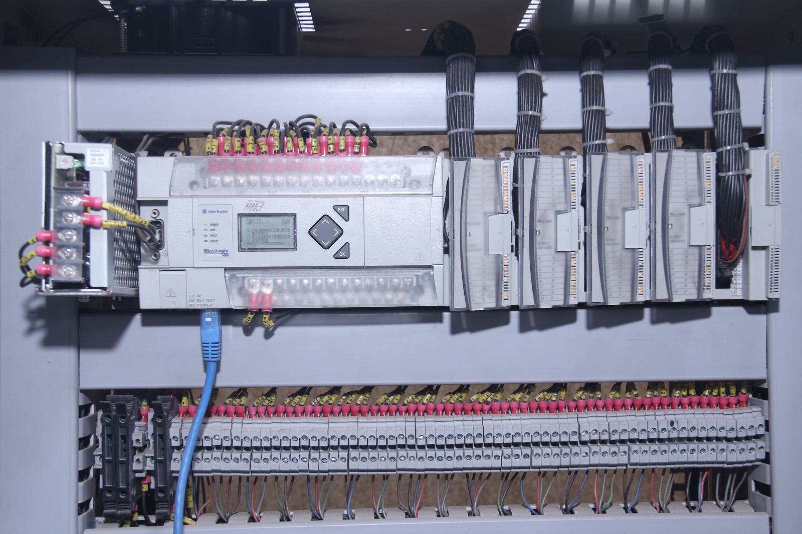
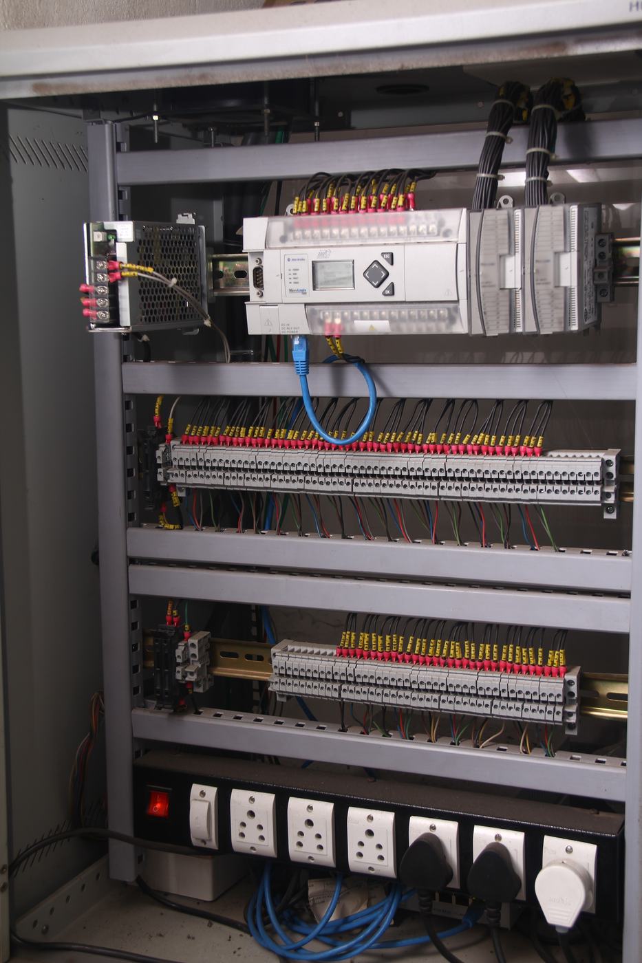
Field. Allen-Bradley MicroLogix 1400 PLCs in each hut, IP-enabled and expandable with digital and analogue I/O cards, wired to spare relay contacts through a tag block.
Network. PLCs as static-IP nodes on a device LAN, extended between huts over existing infrastructure: G.SDHSL modems on a quad-cable copper pair, LAN extenders, Ethernet-to-E1 bridges, or the fibre backbone where the section has one.
Software. An industrial-PC gateway that records all PLC data and keeps a local backup through network outages, and servers on Railnet hosting the database and web application. Any computer at a station, divisional HQ or headquarters becomes an operator terminal, with user access rights. Communication is OPC-compliant, so other vendors’ PLCs and RTUs can join, and concentrators and servers can run dual-redundant or hot-backup.
Each layer can be upgraded without touching the other two. The design also allows non-vital remote control, which SER listed among its goals: changing over the power supply at an auto hut, or operating electric lifting barriers.
| Link between huts | Reach | Ethernet bandwidth |
|---|---|---|
| Copper quad-cable pair, G.SDHSL | Up to 3 km | 256 kbps minimum |
| Single-mode optical fibre | Up to 20 km | Up to 1 Mbps |
| 2.4 / 5.8 GHz industrial radio | Up to 15 km | Up to 1 Mbps |
Distances are between adjacent PLC nodes.
In print
Pilot implementation of IP enabled train monitoring and logging system in automatic signalling section
Shri Ajay Kumar, Chief Signal Engineer, South Eastern Railway. Gyandeep technical magazine, anniversary issue 2013. Indian Railways Institute of Signal Engineering and Telecommunications (IRISET), Secunderabad, pages 85–87.
The article sets out why SER chose a browser-based system in line with Indian Railways Vision 2020, how the Santragachi–Tikiapara pilot was built, and what it did for operations and maintenance. It concludes that the system’s “trouble free working” on SER makes the case for wider adoption.
The same platform, beyond rail
Underneath IPeTMS is our general web-based control and data acquisition platform: IP-enabled PLCs and RTUs on a device LAN, gateway data concentrators that keep a local copy when the network drops, and a central server for browser clients. Legacy Modbus and Profibus devices map onto it through converters.
It suits pipeline monitoring, substation SCADA, distributed plant automation and asset management. Our other monitoring work, cooling-tower telemetry for Paharpur and solar irrigation with IIT Mandi, follows the same pattern of field sensors, a resilient link and a browser view.